Knowledge
Introduction to CNC Machining Process and Relevant Elements
The CNC processing technology knowledge is elaborated in the following six sections:
1. Introduction to CNC processing and its key characteristics
2. Important elements of CNC processing
3. CNC processing parameters
4. Common post-processing steps in CNC processing
5. Basic structural design for CNC processing
6. Preliminary assessment of manufacturability for CNC processing
I. Introduction to CNC processing and its key characteristics
1. Definition of CNC:
Computer Numerical Control, which means Computer Digital Control.
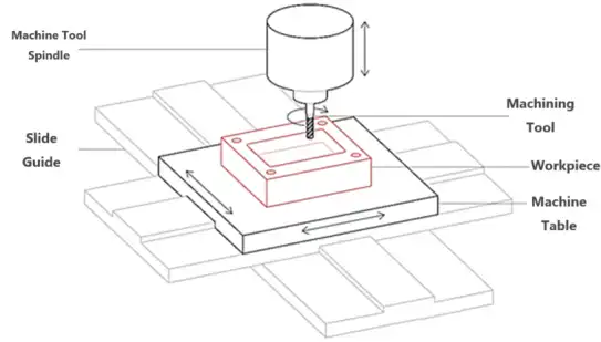
A CNC machine is an automated machine tool controlled by a program. The control system can logically process programs specified by control codes or other symbolic instructions, decode them through a computer, and make the machine perform the prescribed actions. Through the cutting action of the tool, the raw material is processed into semi-finished or finished parts.
CNC processing is a subtractive technology. It uses high-speed rotating tools to remove materials from solid blocks to produce parts according to CAD models.
2. Characteristics of CNC Machining
The parts processed by CNC machining possess high dimensional accuracy and strict tolerances, and are suitable for mass production and one-off work.

II. Key Elements of CNC
CNC Key Elements - Materials
1. Commonly used processing materials in CNC
Metals: Aluminum, Stainless Steel, Brass, Bronze, Copper, Steel
Plastics: ABS, PC, ABS+PC, PP, PS, POM, PMMA, etc.
2. According to the source of materials, they can be classified into the following types:
(1) Sheet materials: processed through simple cutting and machining
Advantages: The material properties are relatively stable, facilitating processing,
Disadvantages: There is a lot of leftover material, the processing time is long, and it is not suitable for large-scale mass production
(2) Profiles: Customized selection based on the structural shape of the product or to reduce the machining milling volume
Advantages: It can greatly reduce the machining allowance and shorten the processing time and cost and raw material cost. It should be vigorously promoted
Disadvantages: The tolerance accuracy of profiles is difficult to ensure, and the appearance effect of grade A cannot be achieved;
(3) Forgings: Mostly formed by forging sheet materials
Advantages: Like profiles, it can also shape the structural shapes that profiles cannot achieve, thus saving materials and time
Disadvantages: There is a certain risk in the conversion of processing benchmarks between forging and CNC machining. The stress increase during the forging process causes the stability of CNC machining to deteriorate;
(4) Stamping blanks: Mostly made from sheet materials (strip materials) and then simple punching and edge cutting are performed
Advantages: It can reduce the machining allowance and time to a certain extent, and provide a rough machining benchmark for CNC machining;
Disadvantages: There is a risk of deformation due to punching and cutting, which causes risks to the positioning of the CNC machining surface.
(5) Die-casting blanks: Mostly for products with high requirements for certain features, the die-casting blanks are processed after the die-casting to achieve the customer's finished product requirements. However, when the processing volume is large, there is a risk of sand holes, and it is necessary to apply to the customer for acceptance standards in advance.
CNC key component - machine tool
Main parameters of the machine tool
• Available power
• Service life/condition - stability
• Horizontal/vertical
• Type and specification of the spindle
• Number and configuration of the shafts
• Clamping of workpieces.
CNC's Key Element - Cutting Tools
1. Common types of milling cutters used in CNC machining centers
(1) End mills / Face mills: They have cutting edges on both the side and bottom surfaces, and can be used for rough and finish machining of the side and bottom surfaces of products. They are suitable for various plane machining such as holes, slots, and cavities, but not for curved surface machining.
(2) Ball nose mills: They are suitable for processing complex three-dimensional shapes but not for processing flat surfaces.
(3) Round nose mills: Also known as flat-bottom R mills, they are used for rough and finish machining of the side and bottom surfaces with R-angled structural features of products.
(4) Forming mills: Special-shaped cutting tools can be customized according to the structural features of products. T-mills, dovetail mills, chamfer mills, etc. are considered special forming mills.
2. Materials of milling cutters:
High-speed steel, cemented carbide, ceramic, cubic boron nitride (CBN), synthetic diamond
3. Selection of Milling Cutters
(1) Common diameters of milling cutters
Diameters of end mills/ball end mills commonly used
Hard materials (steel): D1, D1.5, D2, D2.5, D3, D3.5, D4, D6, D8, D10, etc.
Soft materials (aluminum, copper): D1, D2, D3, D4, D6, D8, D10, etc.
Common diameters of round nose mills
D2r0.5, D3r0.5, D3r0.2, D4r0.5, D4r1, D6r1, D8r1, D10r3, etc.
(2) Principles for Selecting Milling Tools
A larger tool removes more material in one operation, reducing processing time and cost. The principle for tool selection: the large-tool principle, which means the radius of the selected tool is slightly smaller than the radius of the fillet. For example, for a fillet with R2.1, milling tools with diameters of D4, D3, D2, and D1 can be used, but the D4 milling tool is preferred as it has the highest processing efficiency and the minimum allowance for the tool change.
(3) Use of T-shaped Tools and V-shaped Tools
When certain surfaces of the part cannot be accessed directly from above and standard cutting tools cannot be used for processing, T-shaped tools or V-shaped tools are needed for bottom cutting.

T-type knife: The recommended bottom cutting width w should be greater than 3mm and should be an integer.
Cantilever knife: The angle is defined as the size. 45° and 60° are commonly used, and other angles can be customized.
The ratio of the cutting diameter to the shaft diameter is usually 2:1; when performing single-side bottom cutting, sufficient space should be reserved, and it is recommended to be ≥ 4d.
CNC Key Element - Fixture
1. Function of the fixture
(1) Positioning: To position the processed product in the correct position relative to the machine tool and the cutting tools.
(2) Clamping: To tighten the product after positioning, so that the position of the product does not change during the processing.
2. Positioning: In the three-dimensional Cartesian coordinate system, the workpiece has six degrees of freedom. The fixture employs six appropriately distributed supporting points to respectively restrict the six degrees of freedom of the workpiece, thereby completely determining the position of the workpiece within the fixture. (The principle of six-point positioning)
Several forms of positioning
Complete positioning: During processing, all six degrees of freedom of the workpiece are completely restricted.
Incomplete positioning: Under the premise of meeting the processing requirements, the six degrees of freedom of the workpiece are not completely restricted.
Over-positioning: A certain degree of freedom of the workpiece is repeatedly restricted (avoid over-positioning)
Under-positioning: Degrees of freedom that should be restricted according to the processing requirements are not restricted (over-positioning is not allowed)
3. Clamping: To ensure that the workpiece maintains its predetermined position during machining under the influence of external forces such as cutting force, inertial force, and gravity, a clamping device must also be provided on the fixture to exert an appropriate clamping force on the workpiece.
Pneumatic clamping: Its advantages are low cost, high efficiency and wide application; its disadvantages are that it is prone to fail to hold tight when the air pressure is unstable and it is easy to cause damage to the product.
Vacuum clamping: Its advantage is that it will not cause damage to the product; its disadvantage is that the clamping force is relatively weak.
Manual clamping: Its advantage is low cost; its disadvantage is that the operation is complex, the torque wrench force control is not precise enough and it is prone to cause damage.
Electromagnetic clamping: Its advantage is that the clamping force is large; its disadvantage is that the heat generated during operation will lead to the weakening of magnetism, there may be a phenomenon of failure to hold tight, and the cost is high and it is prone to cause damage.
III. CNC Process Parameters
During milling processing, the relative motion between the milling cutter and the workpiece is called the cutting motion; among them, the rotational motion of the milling cutter is the main motion, and the movement or rotation of the milling cutter relative to the workpiece is the feed motion.
(1) Milling speed Vc: The linear speed of the main motion, which is the rotational speed of the milling cutter. It is measured in meters per minute.
Vc = π*d*n/1000 m/min
Spindle speed n: The rotational speed of the milling cutter per minute, measured in revolutions per minute (rpm).
Number of teeth z of the milling cutter.
(2) Feed rate is the displacement of the cutting tool relative to the workpiece in the feed direction.
Per tooth feed rate fz: The displacement of each tooth of the milling cutter relative to the workpiece in the feed motion direction when the cutter rotates one tooth, unit: mm/z
Per revolution feed rate fr: The distance that the workpiece moves relative to the milling cutter in the feed motion direction when the cutter rotates one revolution, unit: mm/r
Per minute feed rate fm: The distance that the workpiece moves relative to the milling cutter in the feed motion direction when the milling cutter rotates for one minute, unit: mm/min. fm has the same meaning as feed speed.
fr = fz * z (mm/r)
fm = fz * z * n (mm/min)
(3) Side cutting depth / Radial cutting depth a_e: The width of the milling cutter diameter participating in the cutting of the workpiece along the radial direction, mm, refers to the distance across the machined surface.
Back cutting depth / Axial cutting depth a_p: It is the metal removal amount of the tool on the workpiece surface, mm. This is the distance from the tool to the unprocessed surface below when the tool enters.
(4) Forward milling: The rotation direction of the milling cutter is the same as the forward movement direction of the workpiece; it can avoid the polishing effect, thereby generating less heat and minimizing the tendency of work hardening.
Reverse milling: The rotation direction of the milling cutter is opposite to the forward movement direction of the workpiece;
The durability of the tool is higher in forward milling. In forward milling, the tool cuts into the workpiece at the beginning, and the cutting thickness changes from thick to thin, with less tool edge wear; while in reverse milling, the cutting thickness gradually increases from zero, due to the existence of the arc radius of the tooth edge, the tool edge presses and rubs on the machined surface, slides for a short distance before cutting into the workpiece, accelerating the tool wear and intensifying the surface hardening degree, affecting further processing.
IV. CNC Post-processing
1. Cleaning of surface oil stains on CNC processed products to prevent corrosion and dirtiness of the products.
2. Remove the residual metal burrs or plastic burrs left after CNC processing. There are methods such as magnetic grinding, rolling grinding, sandblasting, and dry ice deburring.
V. Basic Structure Design of CNC Products
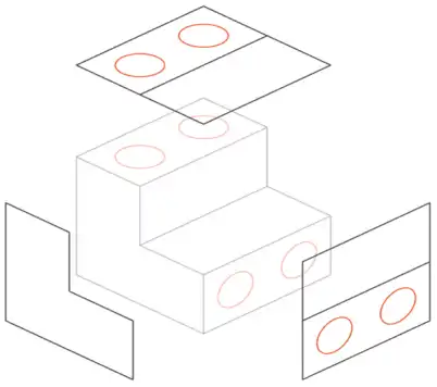
1. Minimize the number of clamping operations as much as possible
The machining path is one of the main limitations in CNC machining. To achieve all surfaces of the model, the workpiece must be rotated and flipped multiple times. Every time the workpiece rotates, the machine tool reference must be recalibrated and a new coordinate system must be defined. (Compared with conventional three-axis machining)
In order to obtain the maximum relative positional accuracy between two or more features, these features must be machined in the same setup. This is because the new calibration step introduces a small (but non-negligible) error, regardless of the high-precision fixtures used. Increasing the number of setups will inevitably affect the accuracy.

2. In the design, avoid deep grooves, deep holes and deep cavities.
Deep narrow grooves must be machined with longer cutting tools. Longer cutting tools are prone to breakage and may cause tool vibration or machine vibration. Machining a deep groove requires several processes, which will increase processing time and manufacturing costs.
When milling relatively deep cavities, problems such as tool sagging, tool skewing, difficult chip removal and tool fracture may occur. Generally, the depth of the cavity is limited to 4 to 5 times its length (i.e., the maximum size on the XY plane), which can achieve the minimum processing cost.
3. Edge Treatment
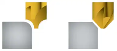
Since all the milling heads rotate as circular rotary bodies, it is impossible to achieve internal acute angles and internal bevel angles. Instead, the milling cutter will leave an unprocessed area (corner) with the same radius as the tool. Using alternative methods such as electrical discharge machining, internal bevel angles or concave grooves without bevels can be machined, but these methods are often costly.
To fully utilize the advantages of larger tools, the maximum radius of the internal rounded corner should be designed, preferably greater than 1.0mm, and the minimum should not be less than R0.5mm.
The chamfers on the top edges of the bosses and grooves require customised equal-diameter forming tools, which are costly. It is recommended to chamfer the edges of the features instead of rounding them off. Exceptions can be made when necessary.

4. Wall Thickness Design
When using metal for milling or CNC machining, thin walls can cause flutter, which will affect the accuracy of the machining process and the surface finish of the parts; for plastics, thin walls can lead to warping and softening.
For metal parts, the wall thickness is recommended to be designed at 0.8mm or more, with the minimum being 0.5mm.
For plastic parts, the wall thickness is recommended to be designed at 1.5mm or more, with the minimum being 1mm.
The high and slender features will undergo significant vibration during processing, resulting in poor tolerance and surface finish. In cases where it is possible, try to reduce the height. It is recommended that H < 4W.
5. Hole Machining
It is divided into standard-diameter holes and non-standard-diameter holes. Standard diameter holes can be machined by drill bits, and the maximum depth of drilling is recommended to be 4 times the nominal diameter; typically, it is 10 times the nominal diameter; and it is feasible for 40 times the nominal diameter.
Reaming cutters and boring cutters are used to machine holes with strict tolerance requirements. It is also recommended to use standard diameters.
Non-standard diameter holes are machined by end milling cutters (subject to the maximum depth limit). Blind holes machined by drill bits have conical bottoms, while holes machined by end milling cutters are flat.

6. Thread Hole Machining
Internal threads can be machined using taps or thread milling cutters. Taps can be used for thread machining of M2 and above, while CNC thread cutting tools can be used for machining threads with the minimum diameter of M6.
To obtain accurate and precise results, deep tapping should be avoided: the longer the tapping depth, the greater the risk of vibration and deviation during operation, which can lead to product defects.
Generally speaking, a thread length that is 1.5 times the diameter can provide sufficient thread engagement, because most of the load applied to the thread is borne by the first few teeth (not exceeding 1.5 times the nominal diameter). The thread length is not recommended to exceed three times the diameter of the cutting tool.
VI. Preliminary Evaluation of the Manufacturability of CNC Products
1. Overall Evaluation
(1) Types of raw material materials
(2) Whether surface treatment is required? (sandblasting? anodizing? spraying? electroplating? etc.)
(3) Does the existing structure of the product meet the requirements for clamping and facilitate the search for processing benchmarks?
(4) Does the 2D drawing indicate the requirements for surface roughness, tolerance of thread holes and form position dimensions? (i.e., additional requirements that cannot be reflected in the 3D drawing)
2. Analysis of Rationality of Common Structures
(1) Does the product have deep groove, deep hole or deep cavity structure? Judge the rationality based on the principle of maximum depth limit.
(2) Does the product have beneficial angle structure? If the internal beneficial angles cannot be machined, R angles need to be added; if the external beneficial angles of the product are prone to collapse or cause safety hazards, it is recommended to prioritize the use of inverted C angles, followed by round angles (the angle of the chamfer needs to be the same, and the external R angles need to consider using forming tools for processing).
(3) Is the R angle of the product structure too small? A small R angle corresponds to a smaller tool, which has weak strength and is prone to breakage and vibration, and has low processing efficiency.
(4) Does the product have thin-walled structure?
(5) Are the features too close to each other? Narrow areas are difficult to machine, and the tool is hard to pass through. Long tools and small tools are prone to breakage and tremor.
(6) Does the front clamping position need to reserve a process station angle for the subsequent clamping position? (Used as the positioning for the rear clamping position; or to increase the structural strength for stable processing and reduce deformation), or to provide a hanging point for subsequent surface treatment processes such as anodizing and electroplating.
If you have any question, demand, related parts development or improve your supply chain, please feel free to contact us info@castings-forging.com


